permalink: /index.html
layout: single
RP2040 VCO
This is a simple digital VCO (Voltage Controlled Oscillator) based on the Seeed XIAO using the RP2040 chip by the Raspberry Pi foundation. This project is a fork of the project by BleepSound, which is in turn a clone by the original project created by HAGIWO (link in japanese).
The module uses mostly SMD components of size 0805.
The resulting module is meant to be used as part of a Eurorack modular synthesizer with a ±12 V⎓ power supply. Alternatively it can be used standalone by using a cheap DC-DC converter from Aliexpress.
Hardware
- powered by ±12 V⎓ (Eurorack Standard)
- 4HP (~20mm) wide
- 3× Potentiometers/Knobs (one with additional CV input, labeled
INV) - 1× independent CV input (labeled
V/OCT) - 1× audio output (AC-coupled)
- 1× push button (momentary)
- 1× toggle switch (3 positions)
Software
This is a digital module, as such one can modify and upload different variants of the original software. At the time there are two variants:
- polyphonic Chord VCO module with 8 different waveforms With a built-in quantizer and automatic harmonics function, if you input a suitable CV, it will play a nice chord progression.
- Drum Module with 3 different Instruments (Kick/Snare/Hihat) Trigger the drum via push-button or external gate signal. Use a the three knobs to change tuning, decay and other sonic characteristics.
Schematic

BoM
Building
- diodes (watch for the orientation!)
- resistors
- DIP chips (watch for the orientation!)
- capacitors (film/ceramic)
- Electrolytic capacitors (watch for the orientation!)
For the next part, place them without soldering them:
- jacks, pots, buttons and switches that go throught the front panel
Once placed, put in place the front panel, then fasten all components to it. Once this is done, you can solder them.
Software upload
Uploading new Software isn't complicated, but a few things need to be in place for it to work
1. Install the Arduino IDE and the Seeed Xiao Board Manager
- Download and install the Arduino IDE for your operating system
- Start the Arduino IDE and go to
File > Preferences- Copy this URL:
https://files.seeedstudio.com/arduino/package_seeeduino_boards_index.jsonand paste it into the text input field at Additional board manager URLs. If there is already text there, go to the very end of the text, type a,there (if there isn't one already) and paste the URL there - Finish the installation of the Seeed Xiao packages
- Copy this URL:
2. Download this Project (which includes the code)
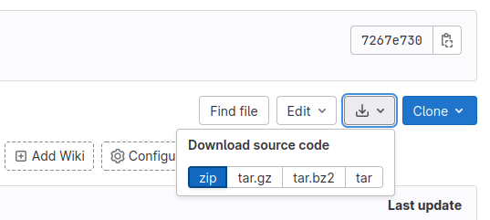
- Click on the Download icon and
zipon the top right of this repository site:
- Unpack the folder stored in the zip file to some location and open it in your file manager
- Go into the sub-directory called
Softand chose which software you want to upload. Doubleclick the file ending in.inoto open it in the Arduino IDE